DMX512 decoder: LED installation and addressing guide
· Guías técnicas
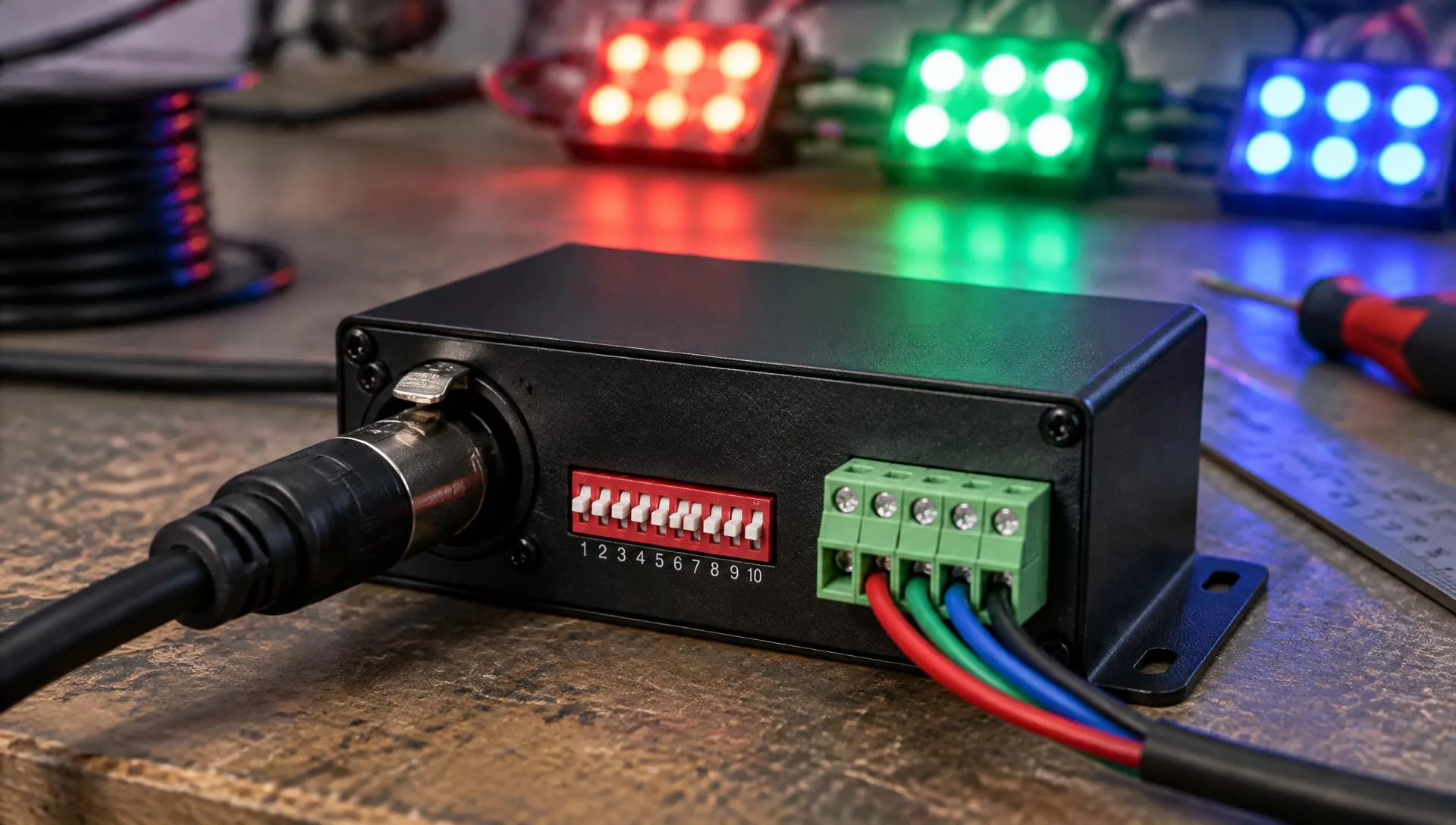
An events hall that changes mood scene after scene, a façade that follows a seasonal campaign or an RGB sign that breathes with the brand colours: behind every one of them there are 1 to 24-channel DMX512 decoders for LED turning console commands into light. This guide covers how to pick the right model, wire it, set its address and fix the faults installers run into most often on site.
In 30 seconds
- One channel per colour: 1 single colour, 3 RGB, 4 RGBW, 5 RGB + CCT.
- Power per channel = voltage × amps: 5 A at 24 V gives 120 W per channel.
- No overlapping addresses: next = current + number of channels.
- Daisy-chained DMX line: max. 32 devices and a 90–120 Ω terminator at the end.
- Parallel load: max. 20 LED modules per line from a distribution block.
A DMX512 decoder is the device that receives the digital signal from a DMX console or controller and turns it into dimmed power for LED strips or modules. Each output takes up one channel of the DMX universe, which holds 512. Decoders are selected by channel count (set by the LED type), amps per channel (set by the load) and operating voltage, usually 12 to 48 VDC. A professional installation combines decoders, power supplies, a daisy-chained, terminated data line and, in large venues, amplifiers that open new branches.
What is DMX512 and what does a decoder do?
DMX512 is the standard control protocol for professional lighting. A single cable carries 512 channels, each with a value from 0 to 255 that sets how bright an output should be. The console does not power the LEDs; it only sends commands. The decoder reads its own channels and regulates the current flowing from the power supply to each colour.
That is why units of different sizes can share one line without conflict: each one listens to its own block of channels starting at its start address.
What types of DMX decoder are there?
The first decision is how many channels you need; the second is how many amps per channel. This table sums up the most common families and the catalogue models in each:
| Channels | Typical use | Models |
|---|---|---|
| 1 channel | Single-colour LED, dimming one zone | D1 · 20 A · D1-L · 10/15 A |
| 3 channels | RGB strips and modules: signs, built-up letters, coves | GPT-1803_C10 · 5 A · D3 · 6 A · D3-XE · 10 A |
| 4 channels | RGBW: saturated colours plus a clean white | D4 · 5 A · D4-E · 8 A · D4-WPS · IP67 |
| 5 channels | RGB + tunable white (CCT): hospitality, retail, stage | D5 · 6 A · D5-E · 4 A |
| 12 / 24 channels | Many independent runs from a single unit: façades, venues | D12 · 5 A · D24A · 5 A |
| Constant current | 350–3000 mA downlights and luminaires, not 12/24 V strips | D1C-E · D4C-1200 |
Constant-voltage (CV) decoders drive 12/24 V strips and modules; constant-current (CC) decoders are for luminaires that need 350, 700 or 1,050 mA. Mixing them up damages the LEDs, so always check the datasheet.
How do you choose the right decoder?
1. Number of channels
Count colours and zones. An RGB cove that changes all at once needs 3 channels; split it into four runs that move separately and you need 12 channels: four 3-channel decoders or one 12-channel unit.
2. Amps per channel and power
The maximum power of each output is voltage × amps. Run it at 80 % to extend the life of the unit. Example with a 3-channel, 5 A RGB decoder such as the 5–24 VDC GPT-1803_C10:
| Voltage | Per channel | Maximum (3 channels) | Recommended (80 %) |
|---|---|---|---|
| 5 VDC | 25 W | 75 W | 60 W |
| 12 VDC | 60 W | 180 W | 144 W |
| 24 VDC | 120 W | 360 W | 288 W |
If the load exceeds what one channel can deliver, move up to an 8 or 10 A per channel model, split the installation across several decoders or switch to 24 V. 12 V and 24 V LED power supplies with 20 % headroom complete the calculation.
3. Voltage, IP rating and connectors
12–48 V models allow longer runs with less voltage drop. IP67 versions are available for outdoor use, and for desks and racks check whether the input is 3 or 5-pin XLR, RJ45 or screw terminals.
How do you wire a DMX decoder to LEDs?
The installation has three parts: power, LED output and data line. The power supply must match the LED voltage, and the outputs are distributed from a distribution block into parallel lines.
- Power: +V and GND from the supply to the decoder input, observing polarity.
- LED output: common +V and colour channels to a distribution or terminal block.
- Distribution: parallel lines of no more than 20 modules each.
- DMX data: D+, D− and GND daisy-chained from unit to unit, terminated at the end.
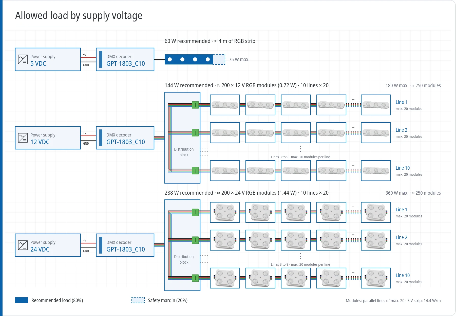
Never connect every module in one long chain from a single end: the last ones come out dimmer and shift in colour. We explain why in our guide to connecting LED modules in series with up to 20 per line.
Recommendation
DMX512 decoders for every project
From 1 to 24 channels, 3 to 20 A, IP67 and constant-current versions. We help you choose the model and the power supply.
View DMX decodersHow is the DMX address set?
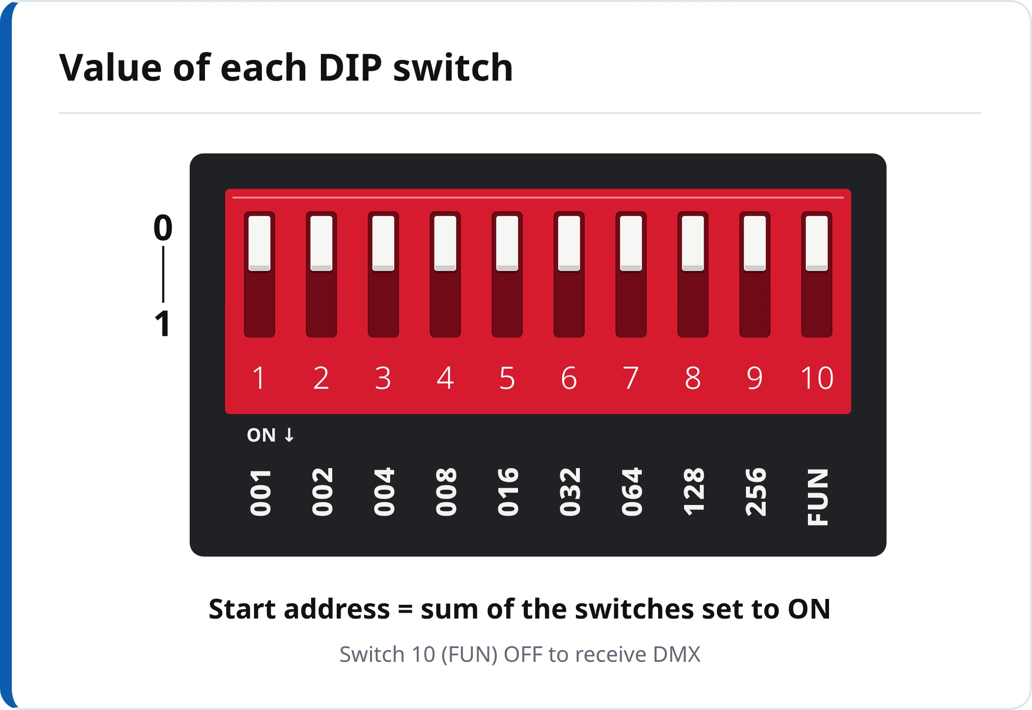
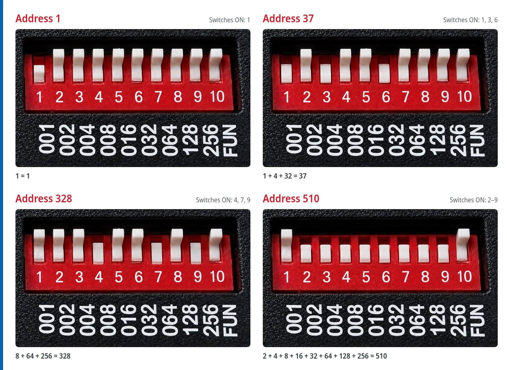
Depending on the model, the address is set with DIP switches, with a display and buttons, or remotely over RDM. The principle is always the same: tell the unit which channel it listens to first. With DIP switches, each of the first nine carries a value and the address is the sum of those set to ON.
Worked addressing examples
- Address 1: only switch 1 ON.
- Address 4: only switch 3 ON. This is the second RGB unit on the line.
- Address 37: 1 + 3 + 6 ON (1 + 4 + 32).
- Address 328: 4 + 7 + 9 ON (8 + 64 + 256).
- Address 510: switches 2 to 9 ON; the last usable address for a 3-channel unit.
How do you connect several decoders on the same line?
The signal leaves the console and passes from one unit to the next in a daisy chain. Each decoder is addressed as many positions above the previous one as channels it uses: 1, 4, 7, 10… for RGB; 1, 5, 9… for RGBW. If you want several units to do exactly the same thing, they can share an address.
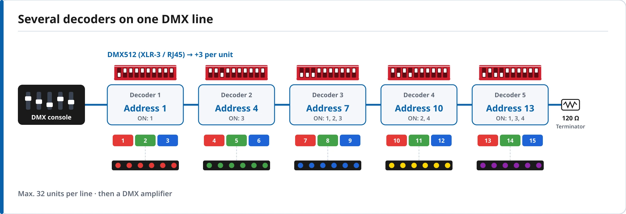
Above 32 devices, or when you need branches to different areas of the venue, use a 4-output DMX512 amplifier splitter. Each output is a new line with its own terminator.
How can you test the installation without a console?
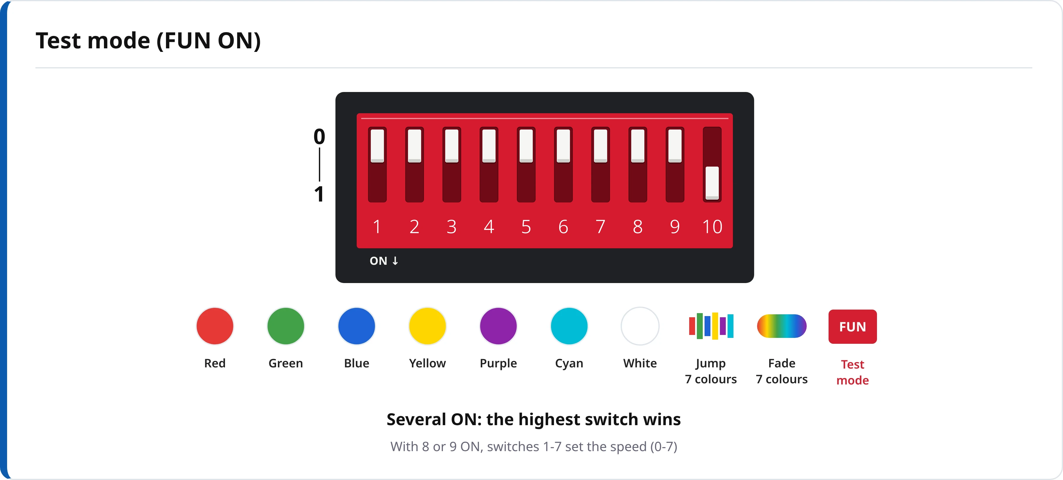
Many decoders include a test or stand-alone mode so you can check in the workshop that every channel lights its colour. On the GPT-1803_C10 it is enabled with switch 10 (FUN) ON: switches 1 to 7 show red, green, blue, yellow, purple, cyan and white; switch 8 starts the 7-colour jump and switch 9 the fade, with 8 speeds. When you are done, set FUN back to OFF and set the final address.
What else does a professional DMX installation need?
For small projects a 6-channel DMX512 console is enough; larger installations use controllers with programmed scenes. For the light itself, 12 V and 24 V IP67 RGB LED modules are the natural match for signs and built-up letters. And where an existing installation uses 0-10 V equipment, a DMX512 to 0/1-10 V converter brings it onto the same line.
We will soon publish a dedicated guide to DMX/RDM, the system that lets you set addresses and read the status of every unit remotely from the console.
Next step
Ready to take it to your project?
Our technical team helps you size the installation, choose the right power supply and quote the material in less than 24 h.
Frequently asked questions
How many DMX channels does my installation need?
One for every colour or circuit you want to dim on its own: 1 channel for single-colour LED, 3 for RGB, 4 for RGBW and 5 for RGB plus tunable white (CCT). If one area has several runs that must change independently, multiply by the number of runs or use a 12 or 24-channel decoder.
How do I work out the DMX address with the DIP switches?
Switches 1 to 9 each carry a fixed value: 1, 2, 4, 8, 16, 32, 64, 128 and 256. The start address is the sum of the switches set to ON. For example, ON at 1, 3 and 6 gives 1 + 4 + 32 = 37. On the GPT-1803_C10, switch 10 (FUN) must stay OFF so the unit follows the console.
Why do my RGB LEDs show the wrong colours?
Nearly always the channels are wired the wrong way round: the module's red lead sits on the decoder's green or blue output. Check that R, G and B match the module wires and that the common positive (+V) goes to the right terminal. The decoder's test mode lets you identify each channel in seconds.
Why do the lights flicker or behave erratically?
Typical causes are a DMX line with no termination resistor (90–120 Ω) on the last unit, unshielded cable, star wiring or more than 32 devices on one line. The signal must be daisy-chained from unit to unit and, if you need branches, split through a DMX amplifier or splitter.
Why are the last LED modules dimmer than the first ones?
That is voltage drop: the current travels through too many modules from a single feed point. Split the load into parallel lines of no more than 20 modules from a distribution block, and use 24 V on large installations, because the same power then needs only half the current.
The decoder ignores the console: what should I check first?
Make sure it is not in test or stand-alone mode, that its address matches the one programmed on the console, that the D+ and D− data wires are not swapped and that the power supply delivers the LED voltage. On long lines, also check the termination and the condition of the cable.