GPT-1803_C10 DMX512 decoder: 3 RGB channels at 5 A for LED strips and modules
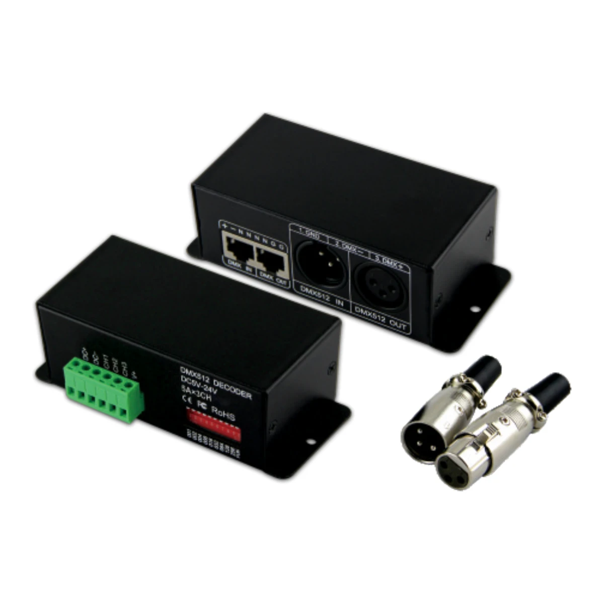
The GPT-1803_C10 is a constant voltage DMX512 decoder that turns the signal from a lighting console, DMX controller or PC software into three independent 5 A PWM outputs. It brings 5, 12 or 24 V DC RGB LED strips and modules into a professional DMX installation, with 256 dimming levels per channel and quick addressing by DIP switch.
Where it fits
- RGB signs and light boxes that must stay in sync with the rest of the lighting in a venue or event.
- Indoor architectural lighting: bars, clubs, hotels, shop windows, retail spaces and showrooms.
- Stages, studios and exhibition stands where the DMX console controls each colour zone separately.
- Three independent single-colour circuits (for example, three zones of white strip) dimmed from the same console.
How much LED strip or how many LED modules you can connect
Each channel delivers up to 5 A, so the maximum power depends on the supply voltage. To keep the decoder cool and leave headroom, size the load at 80% of its capacity.
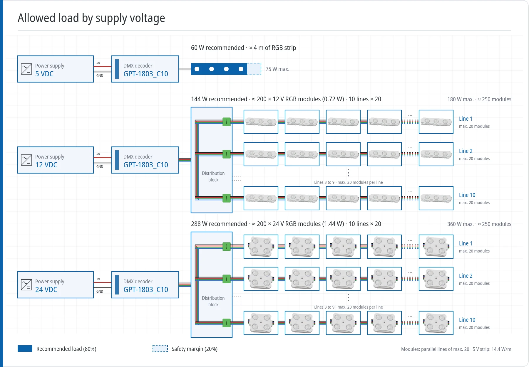
| Voltage | Maximum power | Recommended load (80%) | Load example |
|---|---|---|---|
| 5 V DC | 75 W | 60 W | ≈ 4 m of 14.4 W/m RGB strip |
| 12 V DC | 180 W | 144 W | ≈ 200 × 12V 0.72 W RGB modules in 10 parallel lines of 20 (250 maximum) |
| 24 V DC | 360 W | 288 W | ≈ 200 × 24V 1.44 W RGB modules in 10 parallel lines of 20 (250 maximum) |
On long runs, feed the strip from both ends to avoid voltage drop and colour shift between the start and the end. With LED modules, split the load into several lines of no more than 20 modules, wired in parallel to the decoder output instead of chaining every module on a single line.
Setting the DMX address with the DIP switch
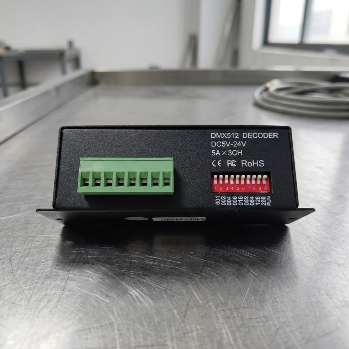
The decoder uses 3 consecutive DMX addresses (red, green and blue). The start address is set with switches 1 to 9, which work in binary: switch 1 is the lowest value and switch 9 the highest. A switch pushed down (ON, position "1") adds its value; pushed up (position "0") it counts as zero. The start address is the sum of every switch set to ON. Switch 10 (FUN) must be OFF for the unit to follow the DMX signal.
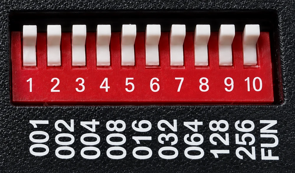
Start address = sum of the switches set to ON. Switch 10 (FUN) OFF to receive DMX.
| Switch | 1 | 2 | 3 | 4 | 5 | 6 | 7 | 8 | 9 |
|---|---|---|---|---|---|---|---|---|---|
| Value when ON | 1 | 2 | 4 | 8 | 16 | 32 | 64 | 128 | 256 |
Addressing examples
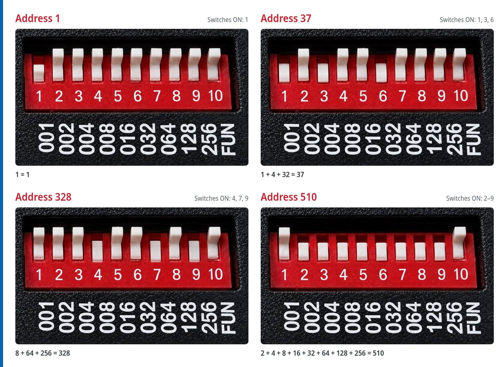
| Start address | Switches ON | Sum | R / G / B channels |
|---|---|---|---|
| 1 | 1 | 1 | 1 / 2 / 3 |
| 37 | 1, 3 and 6 | 1 + 4 + 32 | 37 / 38 / 39 |
| 328 | 4, 7 and 9 | 8 + 64 + 256 | 328 / 329 / 330 |
| 510 | 2 to 9 | 2 + 4 + 8 + 16 + 32 + 64 + 128 + 256 | 510 / 511 / 512 |
The highest usable start address is 510: at 511 the blue channel would fall outside the 512-channel DMX universe.
Several decoders on one line
To control each zone separately, add 3 to the previous decoder's address. Giving several units the same address makes them all show the same colour, which is handy for grouping runs that must stay in sync.
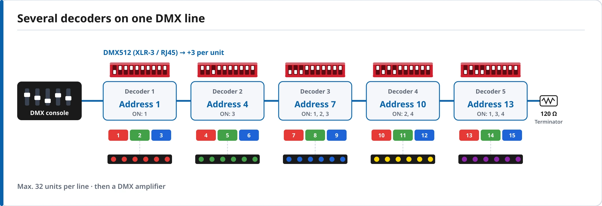
| Decoder | Start address | Switches ON |
|---|---|---|
| 1 | 1 | 1 |
| 2 | 4 | 3 |
| 3 | 7 | 1, 2 and 3 |
| 4 | 10 | 2 and 4 |
| 5 | 13 | 1, 3 and 4 |
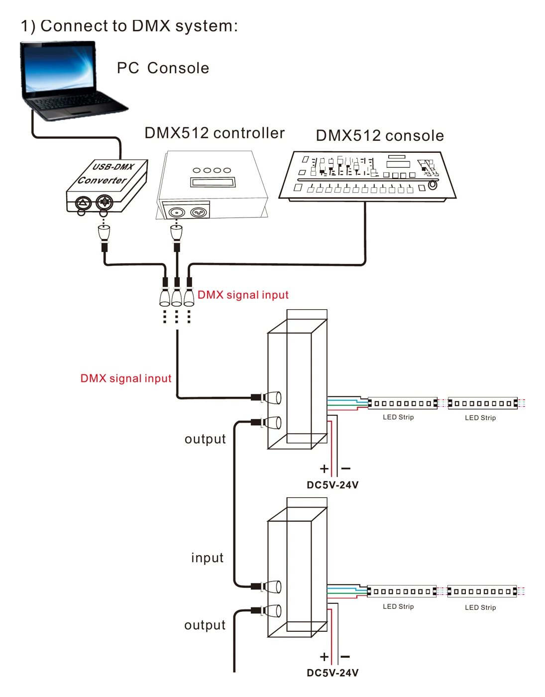
One DMX universe can address up to 170 independent decoders (512 ÷ 3), but each physical line carries a maximum of 32 units; beyond that you need a DMX signal amplifier.
Test mode: check the wiring without a DMX console
With switch 10 (FUN) set to ON, the decoder ignores the DMX signal and enters test mode. You can check the strip, the power supply and each channel's wiring before the lighting technician arrives.
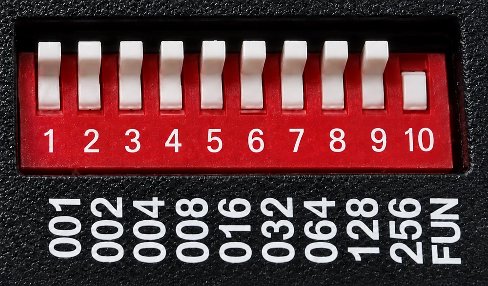
Switch 10 (FUN) ON = test mode. Switches 1 to 9 select the colour or effect.
| Switch ON | Result |
|---|---|
| None (1 to 9 OFF) | Outputs off |
| 1 | Red |
| 2 | Green |
| 3 | Blue |
| 4 | Yellow |
| 5 | Purple |
| 6 | Cyan |
| 7 | White |
| 8 | 7-colour jump (8 speeds) |
| 9 | 7-colour smooth fade (8 speeds) |
When several switches are ON at once, the highest-numbered one wins. With switch 8 or 9 active, switches 1 to 7 set the effect speed: all OFF is speed 0, and the highest switch set to ON gives the speed (1 to 7). For example, with FUN, 9 and 7 ON, the decoder runs a 7-colour fade at speed 7.
Step-by-step wiring
- Switch off the power supply before wiring.
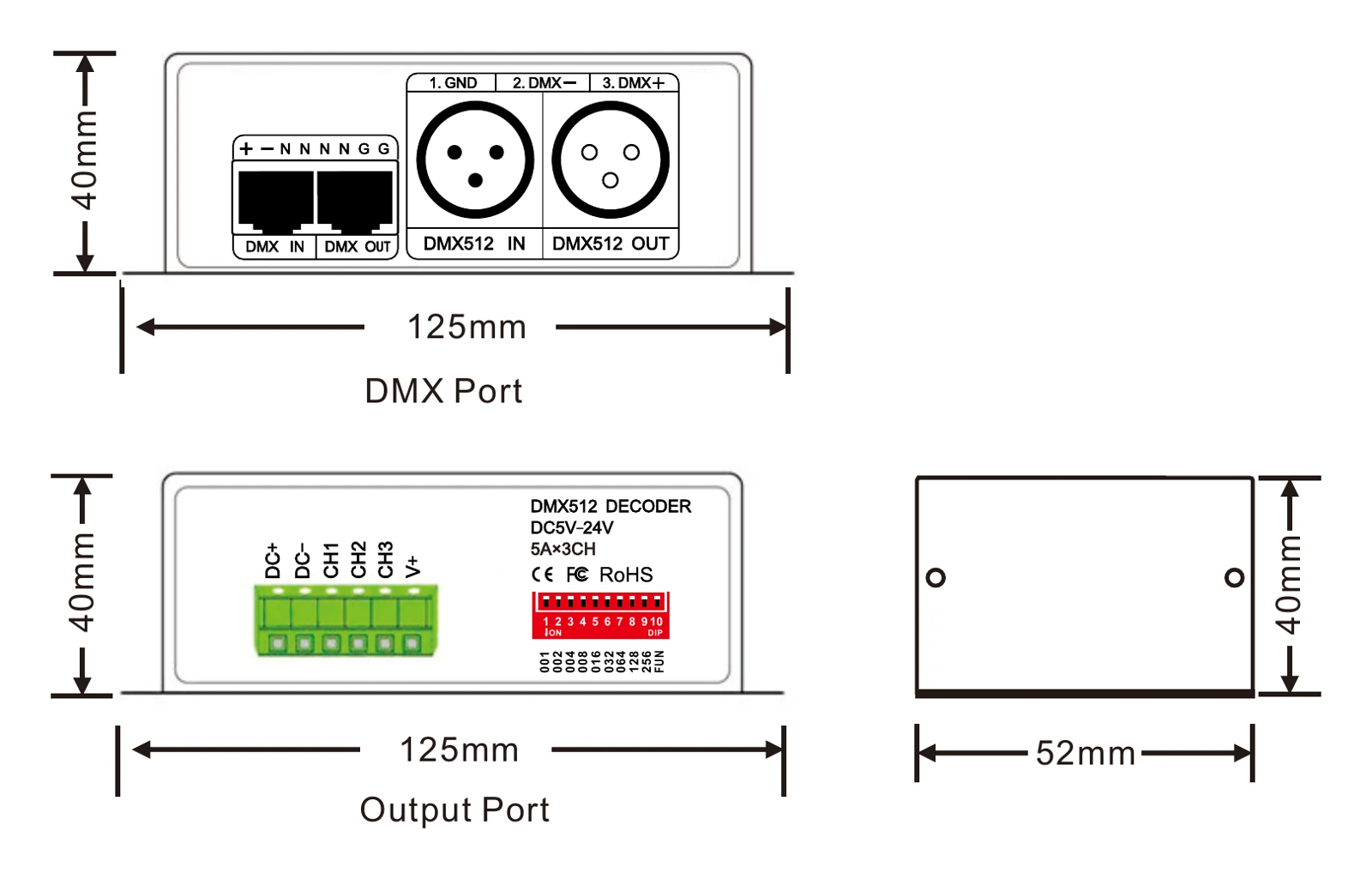
- Connect the constant voltage supply output to the DC+ and DC− terminals. Match the strip voltage: the decoder passes its input voltage on to the LEDs.
- Connect the strip's common positive to V+ and the red, green and blue wires to CH1, CH2 and CH3.
- Bring the console signal into the DMX input (XLR-3 or RJ45) and continue to the next decoder from the output.
- On the last unit of the line, fit a 90-120 Ω, 0.25 W terminating resistor, especially on long runs.
- Set the address with switches 1 to 9, leave FUN OFF and power up.
Common mistakes to avoid
- FUN left ON: the unit stays in test mode and ignores the console.
- Overlapping addresses: if the second decoder starts at 2 or 3, it shares channels with the first one and the colours mix.
- Common-cathode strip: the GPT-1803_C10 works with common anode (common positive); a common-cathode strip will not work.
- More than 5 A per channel: split the load across several decoders or add RGB amplifiers.
Build and reliability
Metal housing measuring 125 × 52 × 40 mm with fixing tabs, for indoor installation (IP20) in cabinets, ceiling voids or sign boxes. It remembers its last state after a power cut, carries CE, FCC and RoHS certifications and comes with a 3-year GP Trader warranty, shipped from our warehouse in Spain.