Connecting LED modules in series: installation guide
· Guías técnicas

Lighting with 12V LED modules with 160°–170° wide-angle lens and IP67 is the undisputed standard in signage, channel letters, light boxes and advertising displays. Their compact size and sealed construction make it possible to evenly illuminate diffusing surfaces such as opal methacrylate or backlight canvas. However, one of the most frequent workshop mistakes lies in how the chains are wired: exceeding the module limit per run, miscalculating the runs or ignoring voltage drop in direct current.
In 30 seconds
- · Maximum 20 12V LED modules per line and injection point.
- · For 40 modules, feed at the center: two runs of 20.
- · Size the power supply with the 80% rule (at least 20% headroom).
- · Module spacing: dx ≤ 1.5 × box depth (dz).
- · More than 20 modules in series from one end = brightness gradient, overheating and failure risk.
Connecting LED modules in series means running chains of 12V modules one after another on the same two-wire bus, respecting a limit of 20 modules per current injection point. Although the modules are electrically wired in parallel, currents accumulate in the first cable sections, which have a small cross-section (18–22 AWG). For 40-module chains, the professional solution is to inject power at the center of the chain with a 1.5–2.5 mm² cable, so that no section carries more than 20 modules.
1. Series or parallel? How 12V LED modules work internally
In workshop slang we say "connecting modules in series" to describe laying out the chain by joining the pre-installed wires of one module to the next. But electrically, 12V LED modules are wired internally in parallel: each module carries its own resistors or constant-current controllers and receives positive (+) and negative (−) continuously along the two-wire bus.
This has three practical consequences:
- Constant working voltage: each module is designed to operate nominally at 12V DC.
- Cumulative current: as modules are added to the same line, the currents add up. A 1.08 W module draws 0.09 A at 12V; a 20-module chain demands 1.8 A in total.
- The conductor bottleneck: the wires joining the modules have a small cross-section (typically 18–22 AWG, i.e. 0.33–0.75 mm²). They are fine for a limited group, but their ohmic resistance limits how much current can flow through the first section without overheating or losing voltage.
For this technical reason, manufacturers set a maximum limit of consecutive modules per current injection point, usually 20 modules at 12V.
2. Scheme A: basic connection of up to 20 modules (end-fed)
The first scheme, universally accepted, consists of connecting a run of up to 20 LED modules fed directly from one end:
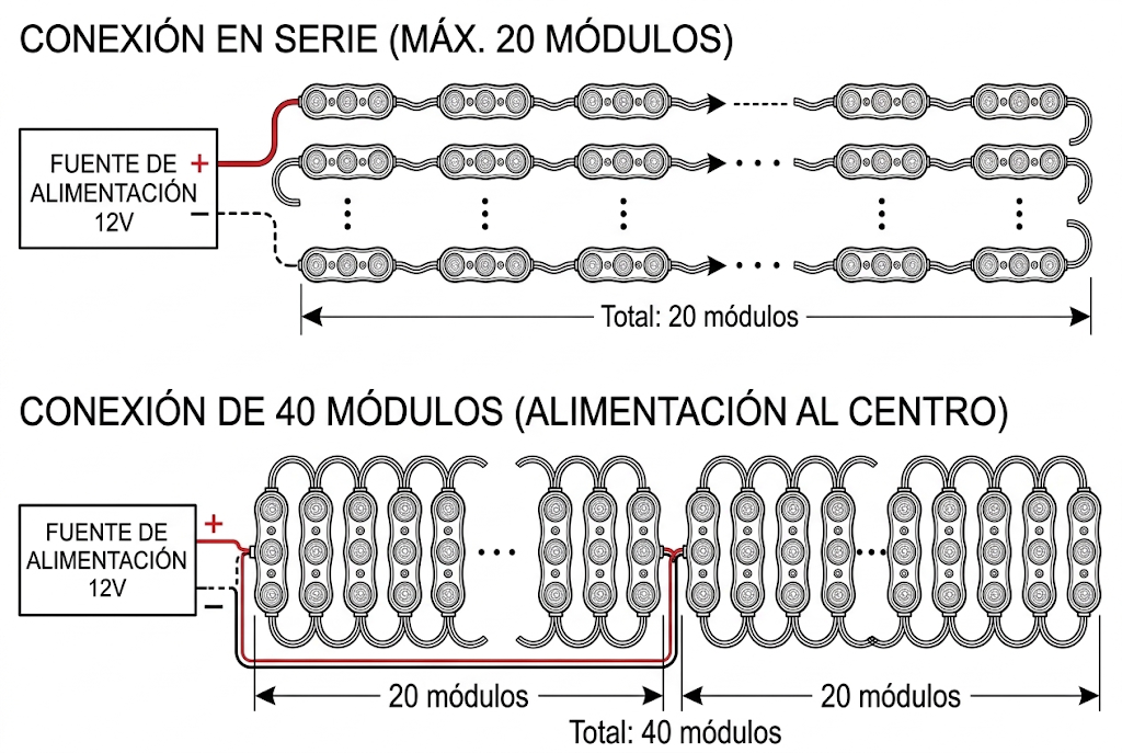
Assembly characteristics:
- Single injection point: the positive and negative wires of the 12V DC supply are spliced at the start of the 20-module chain.
- Zigzag layout: inside the light box or channel letter, the chain spreads into serpentine rows or equally spaced parallel lines, respecting the spacing between module centers (dx) and between rows (dy) according to the box depth (dz).
- End of line: the wires of module number 20 must be cut, insulated and waterproofed to avoid leakage or short circuits against the metal structure.
It is the fastest method to assemble and guarantees barely any voltage fluctuation between the first and the last module, keeping 100% uniform brightness across the whole diffusing surface.
3. Scheme B: connecting 40 modules with center power injection
When the light box requires higher light density or larger dimensions, running an individual feed from the power supply to each group of 20 modules slows down the work. The most efficient technical solution is center feeding or midpoint injection for 40 modules:
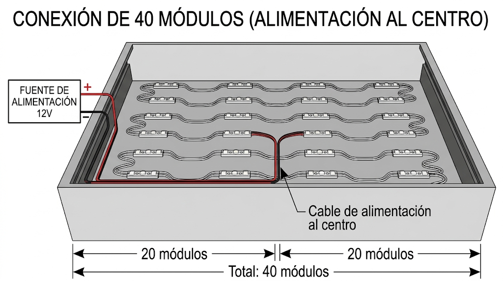
How is it done inside the light box?
- The complete 40-module chain is laid out continuously, covering the bottom of the box in uniform rows.
- From the 12V supply, a main cable of sufficient cross-section (1.5 mm² or 2.5 mm² two-core cable) is run along the side of the box to the exact middle of the circuit, between module 20 and 21.
- At that central point, positive and negative are tapped into the LED chain.
Why does it work so well? By injecting power at the center, the current splits into two opposite runs of 20 modules each. No thin-wire section carries the current of more than 20 modules, the travel length is halved and voltage drop is completely mitigated: 40 perfectly balanced modules with a single trunk run.
Recommendation
12V LED modules with 160° lens and IP67, ready to chain
Injection-moulded modules with pre-installed wires, 3-year warranty and stock in Spain for your next sign or light box.
View LED module catalog →4. Key sizing rules and electrical calculation
For the installation to work reliably for more than 50,000 hours of service life, follow these guidelines:
1. Power supply safety margin (80% rule). Never load a switching power supply to 100% of its rated capacity. With 40 modules of 1.08 W, total consumption is 43.2 W; applying a 20% reserve, the minimum recommended power is 43.2 ÷ 0.80 = 54 W. The right choice is a sealed industrial 60W 12V DC power supply. If you have doubts about the calculation, our guide to sizing the LED driver step by step covers it in detail.
2. Respect polarities. Direct current requires respecting the poles: the wire with a colored stripe or rib is usually the positive (+12V) and the plain white or grey one the negative (GND). Reversing polarity on modules with protection prevents them from lighting; on unprotected models it can damage internal components.
3. Balanced light distribution (dx, dy, dz). To avoid the "zebra shadow" effect or hot spots on the front face, the spacing between modules (dx) and between rows (dy) must be proportional to the usable box depth (dz). With 160°–170° lenses, the practical rule is dx ≤ 1.5 × dz.
| No. of modules (1.08 W/unit) | Total consumption | Minimum supply (80% rule) | Recommended scheme |
|---|---|---|---|
| 20 modules | 21.6 W | 27 W → 30–35 W supply | End-fed |
| 40 modules | 43.2 W | 54 W → 60 W supply | Center-fed (2 × 20) |
| 60 modules | 64.8 W | 81 W → 100 W supply | Three lines of 20 or multiple injection |
5. What happens if I connect 40 modules or more in series from one end?
The first serious problem is the severe voltage drop caused by conductor resistance. At 12 volts DC, voltage loss per metre is very sensitive. When feeding 40 modules in a row through the manufacturer's own thin wires, the voltage decays progressively from 12V at the first module to 9.5V or less at the last ones. The result is a disastrous aesthetic defect for the end customer: an asymmetric brightness gradient, where the sign shines brightly on one side and visibly fades towards the other, also shifting the color temperature of the light.
The second critical factor is the premature overheating of the initial wiring and the first modules. The wire leaving module number 1 does not carry only its own consumption, but the sum of the currents of the remaining 39. That excess current subjects the first centimetres of wire and the tracks of the first PCBs to constant thermal stress through the Joule effect: the insulation degrades, the first diodes work above their design limit and lumen depreciation accelerates drastically, reducing operational life to a fraction of the specification.
Finally, this configuration multiplies the risk of destructive failures, leakage currents and fire outbreaks. Sustained heat at the initial joints ends up carbonizing terminals and lifting solder joints, causing short circuits between poles. The power supply then enters overload protection intermittently and leaves the sign out of service; in the worst case, if protections fail or the short circuit is resistive, the plastic of the modules and the overheated wires can melt, rendering the light box useless and leading to costly repairs at height.
The workshop conclusion is simple: respect 20 modules per line, inject at the center when going up to 40 and size the power supply with headroom. If you want to calculate how many modules your box or channel letter needs, use the GP Trader LED module calculator, which returns the exact layout according to depth and dimensions.
Next step
Ready to take it to your project?
Our technical team helps you size the installation, choose the right power supply and quote the material in less than 24 h.
Frequently asked questions
How many LED modules can be connected in series on the same line?
The recommended maximum is <strong>20 12V LED modules per line</strong> fed from a single injection point. Beyond that, the resistance of the thin inter-module wires (18–22 AWG) causes an appreciable voltage drop and the last modules shine less than the first. For larger installations, split the load across several lines or inject power at the center of the chain.
Are 12V LED modules connected in series or in parallel?
Although workshop slang says "connecting in series" because the modules are laid one after another, electrically <strong>12V LED modules are wired in parallel</strong>: each one receives positive and negative from the two-wire bus and carries its own limiting resistors. That is why currents add up along the line and the first cable section bears the greatest stress.
How do I connect 40 LED modules without losing brightness?
Use the <strong>center feeding</strong> scheme: lay out the 40-module chain continuously and run a 1.5–2.5 mm² main cable from the power supply to the midpoint (between module 20 and 21). By injecting there, the current splits into two runs of 20 modules and no thin-wire section carries more than the recommended current, keeping brightness uniform across the whole box.
What power supply do I need for 40 LED modules?
Multiply the unit power by the number of modules and apply the 80% rule: the supply must not work at 100% load. For 40 modules of 1.08 W, consumption is 43.2 W; divided by 0.80 that gives a minimum power of 54 W, so the correct choice is a sealed <strong>60W 12V DC</strong> supply. Outdoors or in hot areas, raise the margin to 30–40%.
What happens if I connect 40 LED modules or more in series from one end?
Three problems chain together: first, a <strong>voltage drop</strong> that can leave the last modules at 9.5V or less, with a visible brightness gradient and color shift; second, <strong>overheating</strong> of the initial wiring and the first PCBs, which accelerates lumen depreciation; and third, risk of <strong>short circuits and fire outbreaks</strong> from carbonized terminals, leaving the sign out of service or damaging it irreversibly.
What spacing should there be between LED modules in a light box?
With 160°–170° wide-angle lenses, the practical rule is that the spacing between module centers (dx) should not exceed 1.2 to 1.5 times the usable box depth (dz): dx ≤ 1.5 × dz. In a 100 mm deep box, space the modules 120 to 150 mm apart at most. Greater spacing produces zebra shadows and hot spots visible through the diffusing front.